Handling relationship lines, points and labels
Often, dealing with relationships can lead to an undesired situation: the tangle of lines crossing the database model. This is a common situation because as the model tends to grow, new tables are added, and they are connected by the use of relationships. This causes the difficulty of visually interpreting the model. To ease this issue, pgModeler draws the relationship lines in the orthogonal style by default, and still offers manual tools to organize them. How the lines are handled depends on the line style chosen in the Relationships settings: Orthogonal (the default) or Straight and Curved.
Orthogonal lines
The orthogonal style draws each relationship using only horizontal and vertical segments with rounded corners. pgModeler routes the line automatically, going around the tables (and the layer rectangles of the tables) that are in the way, so the lines do not pass over other objects.
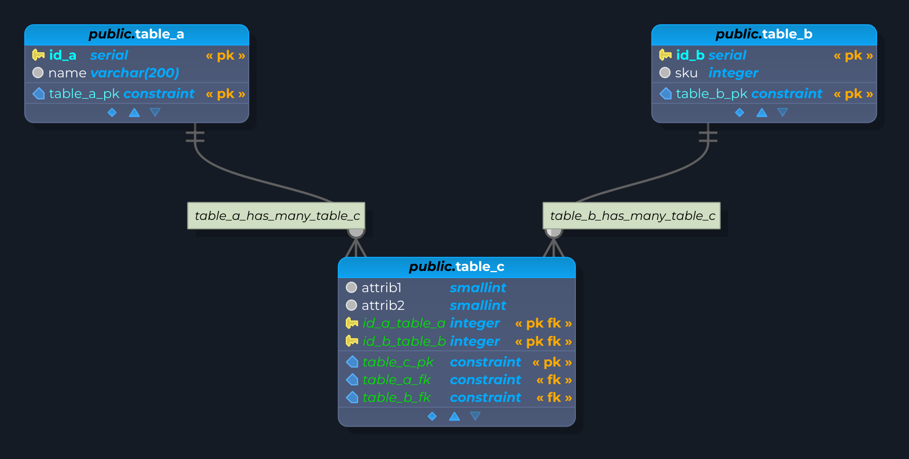
When two lines cross each other, the one that is below hops over the other through a small arc (a bump), which makes clear which line is on top. The routes are recalculated whenever the tables are moved, so there is no need to adjust the lines by hand after rearranging the model.
To adjust the path of a line, hold Shift and drag the segment you want to move. The segments at the ends of the line, next to the tables, are not moved: when they are displaced, the line gets a jog (two extra corners) next to the table and the rest of the segment is moved. The jog itself can be dragged along the line to change the length of the short stretch that leaves the table. To discard all the displacements made on a line and let pgModeler route it again, click the relationship while holding Alt+Shift.
In the orthogonal style the points added with Shift + Click and the Break line feature described below are ignored.
Straight and curved lines
When the style is Straight or Curved, pgModeler offers a feature to break relationship lines at straight angles, facilitating the visualization of the objects. Note that this feature works better when you're using the classical ER notation. If the Crow's foot notation is the one in use, then the line-breaking feature can produce results that may not please some users.
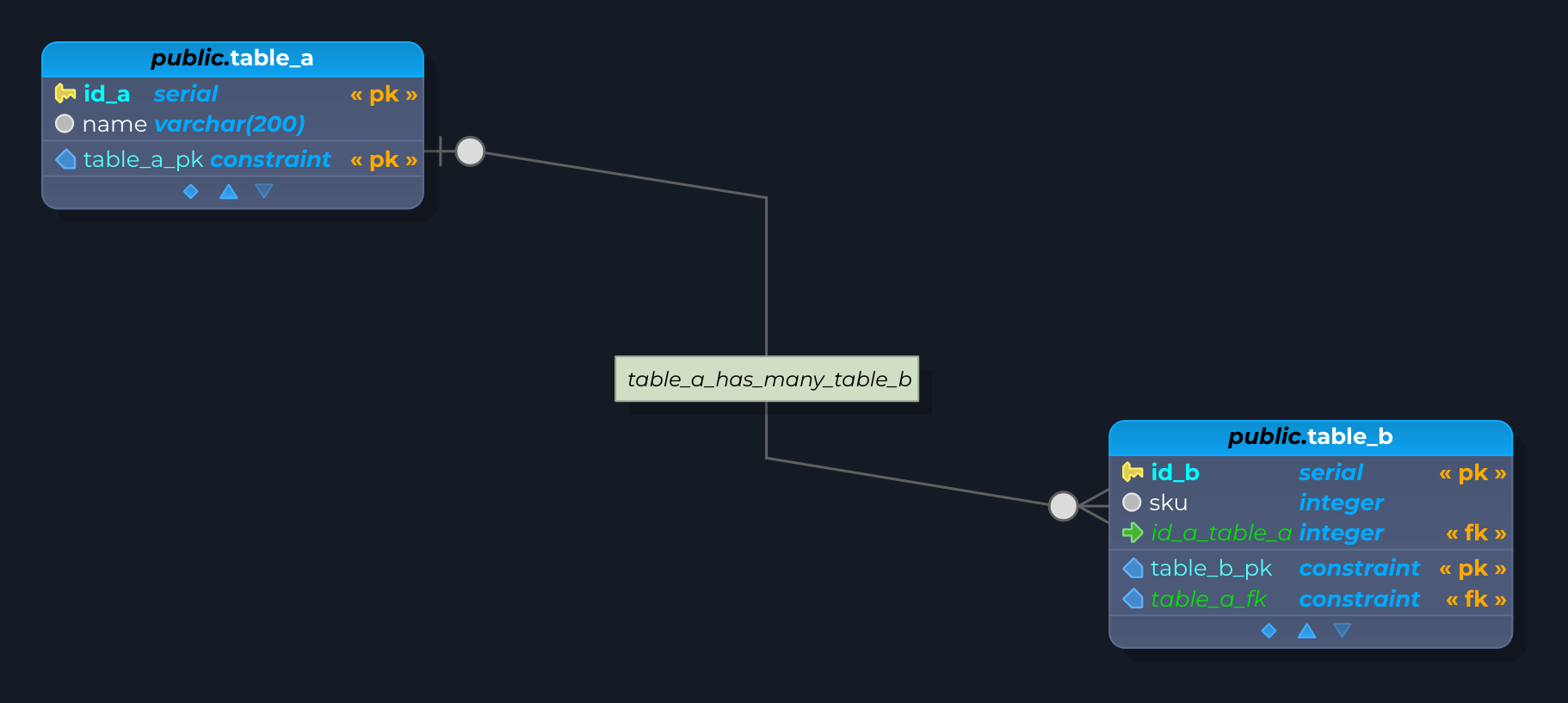
To break the relationship line, the user must right-click the desired object and select one of the modes listed on the submenu Break line: 90° (vertical), 90° (horizontal), 90° + 90° (vertical), and 90° + 90° (horizontal). The first two modes cause the line to be broken into a single ninety-degree line and the last two will break the line into two ninety-degree lines (this is the case in the above image). There is only one prerequisite that must be observed before the use of this feature: the tables must not be in the same vertical and horizontal positions at the same time, or the line break will not have the desired effect.
Another additional feature that helps the model arrangement is the ability to add points to the relationship line by holding Shift and clicking at the desired position on the line. It is possible to move the new point by selecting the relationship again and dragging the point to a new position. To remove all points added by the user, just right-click the relationship and use the Remove points action.
Labels
Finally, you can freely move relationship labels (green boxes in the image). As they are relatively positioned to the relationship line, if the user moves the line, the labels will be moved as well, but without changing their relative positions. To restore the default positions of the labels, just click the relationship while holding Alt+Shift, and they will be moved again to their original positions.