3.10. Relationships
Relationships are the entities used to represent the link between two tables or between a table and a view. To provide ease and flexibility when linking tables, pgModeler implements ten different relationship types, each one with its own semantics, namely: one-to-one (1:1), one-to-many (1:n), many-to-many (n:n), self-relationship, generalization or inheritance, copy, foreign key generated relationship, dependency, identifier, and partitioning.
For some kinds of relationships (1:1, 1:n, n:n), there is a mechanism called column propagation which automatically creates columns and constraints in one of the involved tables. Columns propagated by the relationships are automatically named and graphically represented in a different format (by default, they are the ones with green text color and italic font style). Normally, these objects cannot be modified directly, and in some cases, pgModeler will raise errors if the user tries any operation like deleting or modification over them.
Two special relationships are created automatically in certain cases and cannot have some of their attributes handled directly by the user: foreign-key generated relationships (in short, fk relationships) and relationships between tables and views which are used only to denote the dependency of the view to the linked table.
Relationships can have their own attributes and constraints, where the latter are obligated to be associated with the former. The attributes are converted into columns when the relationship is validated and connected to the tables.
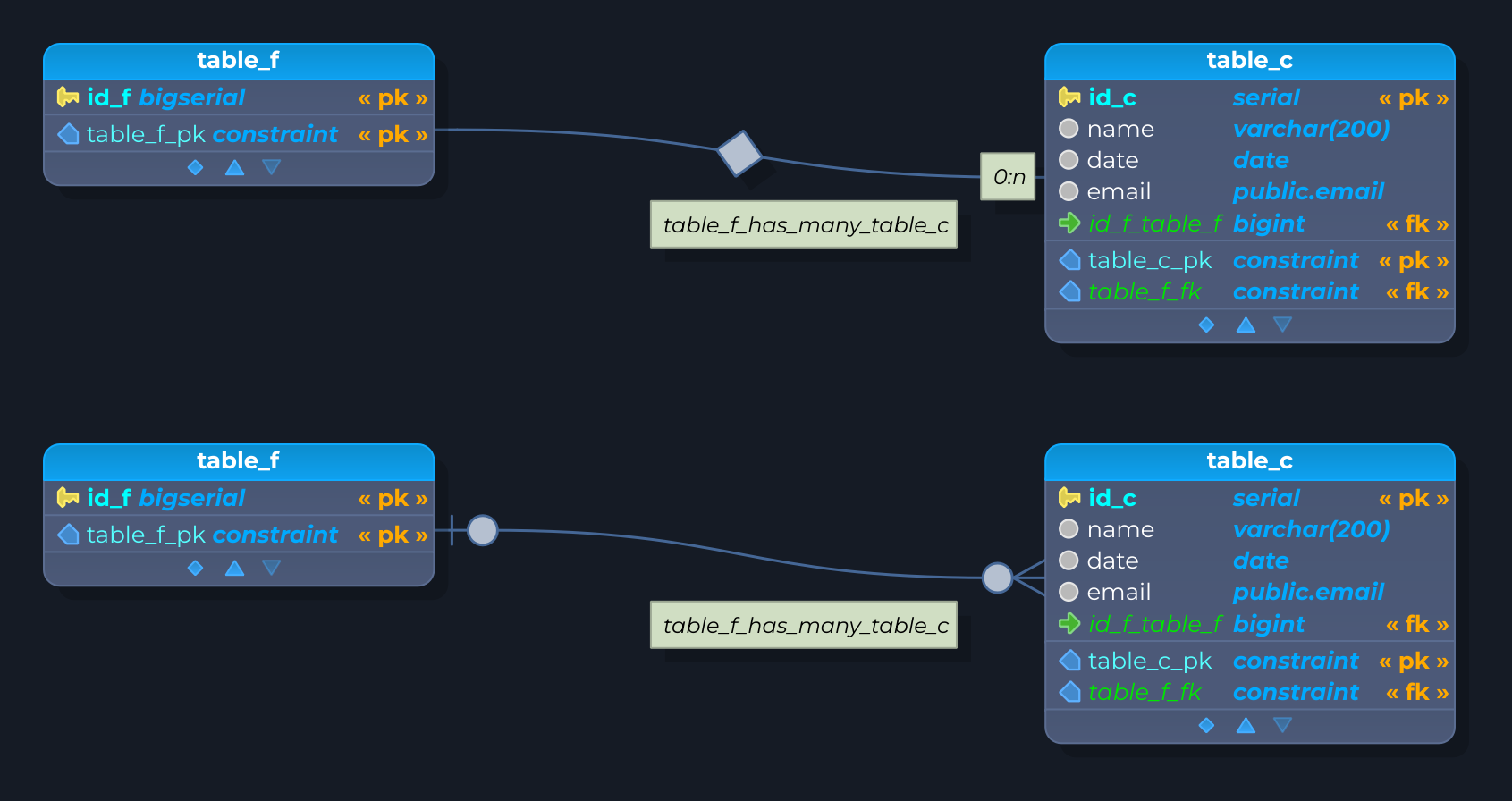
Finally, tables can have optional or mandatory participation in the relationship known as cardinality. Cardinality affects directly all the objects generated by the relationship. In pgModeler, relationships can be represented in two different notations: classical entity-relationship notation and crow's foot notation (see the image below). In the next subsections, all relationship types will be detailed.
One to one (1:1)
The semantics of this relationship can be described as something like this: “an item in table A has linked to it one item of table B”. In practice, foreign key columns in tableB are filled with the values of primary key columns of tableA. The restriction here is that two different items in tableB can't reference the same item in tableA. To ensure this uniqueness, a unique constraint is created and assigned to the foreign key columns in tableB. The column propagation is available for this kind of relationship and depends on the cardinality combination used, as seen below:
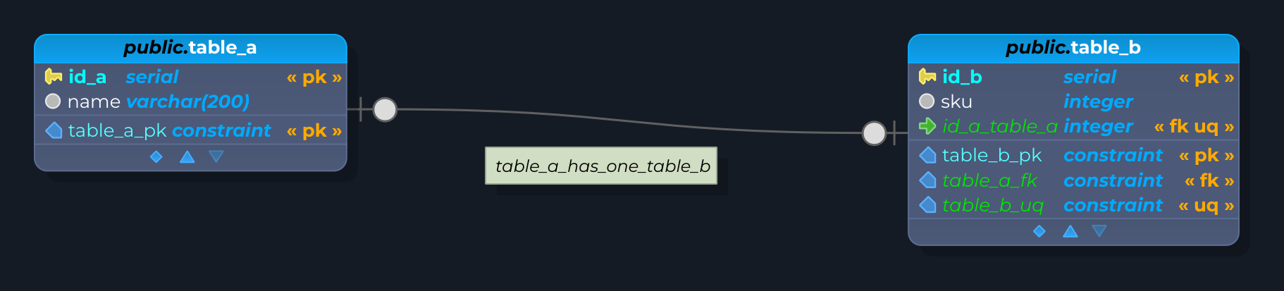
Cardinality: tableA(0,1) —◇— tableB(0,1)
- Columns, attributes, and constraints are always added to the destination table (last selected one –
tableBin the picture above) in order to represent the relationship. - The columns that compose the foreign key accept null values.
- The policy for the
DELETEevent on the foreign key isSET NULL. - The policy for the
UPDATEevent on the foreign key isCASCADE. - A unique constraint is created using the same columns of the foreign key to represent the uniqueness of the entity
tableA. This constraint is added totableB.
Cardinalities: tableA(1,1) —◇— tableB(0,1) and tableA(0,1) —◇— tableB(1,1)
- Columns, attributes, and constraints are always added to the table in which the cardinality is
(0,1)(in the sample image is thetableB). - The columns that compose the foreign key don't accept null values.
- The policy for the
DELETEevent on the foreign key isRESTRICT. - The policy for the
UPDATEevent on the foreign key isCASCADE. - A unique constraint is created using the same columns of the foreign key to represent the uniqueness of the entity, in which the cardinality is
(1,1).
Cardinality: tableA(1,1) —◇— tableB(1,1) [not implemented]
- This cardinality combination is not implemented because it requires merging the involved tables, which may break the user's modeling. An error will be raised if the user persists in the creation of a relationship with this cardinality.
One to many (1:n)
The semantics of this relationship is: “An item in table A has linked to it many items of table B”. To clarify, unlike the one-to-one relationship, foreign key columns in tableB are filled with the values of primary key columns of tableA, and tableB is allowed to have one or more items that reference the same item in tableA. Like the one-to-one relationship, the cardinality affects how columns and constraints are propagated as detailed below:
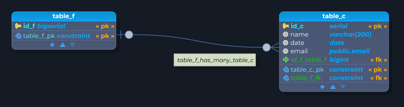
Cardinality: tableA(0,1) —◇— tableB(0,n)
- Columns, attributes, and constraints are always added to the destination table or to the
(n)side (tableBin the sample image above) to represent the relationship. - The columns that compose the foreign key accept null values.
- The policy for the
DELETEevent on the foreign key isSET NULL. - The policy for the
UPDATEevent on the foreign key isCASCADE.
Cardinality: tableA(1,1) —◇— tableB(0,n)
- Columns, attributes, and constraints are always added to the destination table or the
(n)side (tableBin the sample image) to represent the relationship. - The columns that compose the foreign key don't accept null values.
- The policy for the
DELETEevent on the foreign key isRESTRICT. - The policy for the
UPDATEevent on the foreign key isCASCADE.
Note: On the one-to-many relationships, only the “1” side can have the cardinality changed. For the “n” side, the cardinality is always the same (0,n).
Many to many (n:n)
The semantics of this relationship is: “many items in table A have linked to them many items of table B”. This kind of link creates an intermediate table to simulate the relationship between the involved tables. Thus, the foreign key columns on the intermediate table are filled with the values of the primary key columns of both tableA and tableB. The cardinality is ignored for this kind of relationship.

Cardinality: ignored
- An intermediate table is created to represent this kind of relationship.
- Two foreign keys are created on the intermediate table, each one referencing the involved tables.
- A primary key is created on the intermediate table using the columns that compose both foreign keys.
- User-defined attributes and constraints are added to the intermediate table.
- The policy for the
DELETEevent on the foreign keys isRESTRICT. - The policy for the
UPDATEevent on the foreign keys isCASCADE.
Note: The intermediate table can't be edited directly by the user, so if you need to fine-tune its attributes you need to convert the many-to-many relationship to a one-to-many from tableA to the intermediate table and another one-to-many that links tableB and the intermediate table. To convert the relationship, just right-click the desired many-to-many relationship and select Convert.
Self-relationship
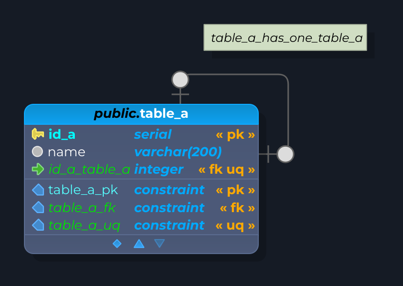
A self-relationship works like the regular 1:1, 1:n, and n:n relationships, which means that all the rules of cardinality and object creation applied to them are valid for this kind. The difference is that only one table is involved and it is linked to itself. To create a self-relationship the user should press and hold the Shift key when using the relationship tool before clicking the desired table. The image below shows an example of a self-relationship.
Inheritance
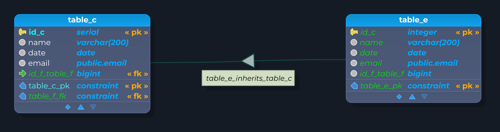
This kind of relationship implements the table inheritance as PostgreSQL does. Visually, columns are copied from the parent table to its child, in the image below, from tableA to tableB. One point must be observed here: the columns are copied to the child table but will not appear in the generated SQL code since PostgreSQL is responsible for handling the inherited columns. Also, as in PostgreSQL, if the same columns exist on both tables, they will be merged on the child only if their data types are the same. In practice, the columns on the child table are kept in their original configuration. When the columns are incompatible, pgModeler will raise an error and abort the relationship creation.
Finally, when creating an inheritance between tables, only check constraints are copied to child tables, if and only if the No inherit attribute is unchecked in these constraints. Other kinds of constraints aren't copied and the user must recreate them on the child table if they are needed; thus, it's quite important to be careful when handling multiple inheritances due to this side effect.
Copy relationship
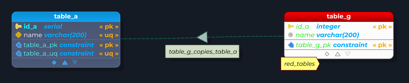
Copy relationship partially implements the table copy as PostgreSQL implements it through the usage of the LIKE keyword. Unlike inheritance, a copy relationship will not merge columns that already exist on the derivative tables; instead, an error will be raised because the premise of copy is to create a table completely decoupled from its parent one.
Observe the slight difference between an inheritance relationship in the previous section and the copy relationship in the image below. The dashed line of the latter only denotes a transient dependency between the involved tables because the child depends on the parent only at design time due to internal validation reasons. When the model is exported to SQL code, two decoupled and independent tables will be created. Even the reverse engineering feature isn't able to identify if a table was created from a copy relationship.
FK relationship
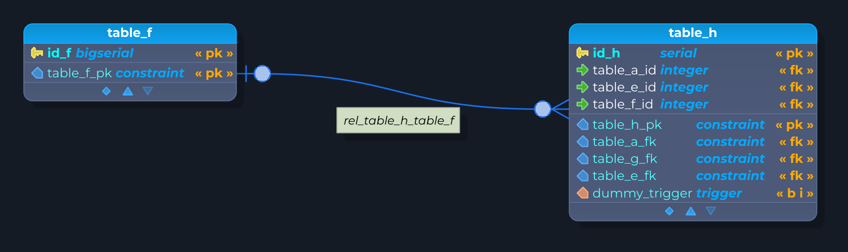
This special relationship has its semantics and rendering defined by the combination of the constraints (primary key, foreign key, unique, and not null) presented in the tables. So, based on this situation, pgModeler will render an fk relationship as one-to-one or one-to-many (including their cardinality variation - optional or mandatory) just by analyzing the mentioned constraints. In the image below we can see four different fk relationships that represent, respectively, (0,1) —◇— (0,n) (green), (1,1) —◇— (0,n) (red), (1,1) —◇— (0,1) (purple), (0,1) —◇— (0,1) (orange).
FK relationships can't be directly modified by the user, except for their basic attributes like the name, line color, and position of the labels, for example. This kind of object is automatically created whenever the user manually adds a foreign key to a table; thus, pgModeler detects which table is being referenced in the foreign key constraint and links the two tables. Unlike the original one-to-one and one-to-many relationships, this one doesn't accept extra attributes or constraints. The only special behavior of this relationship is that if the user deletes it from the model, the foreign key that generated it will be wiped out from the table as well.
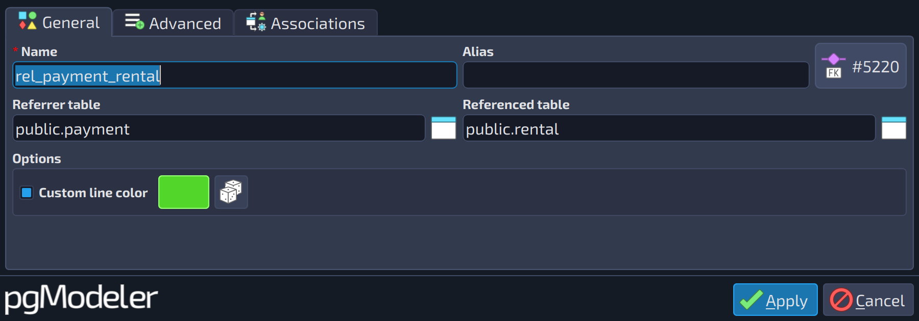
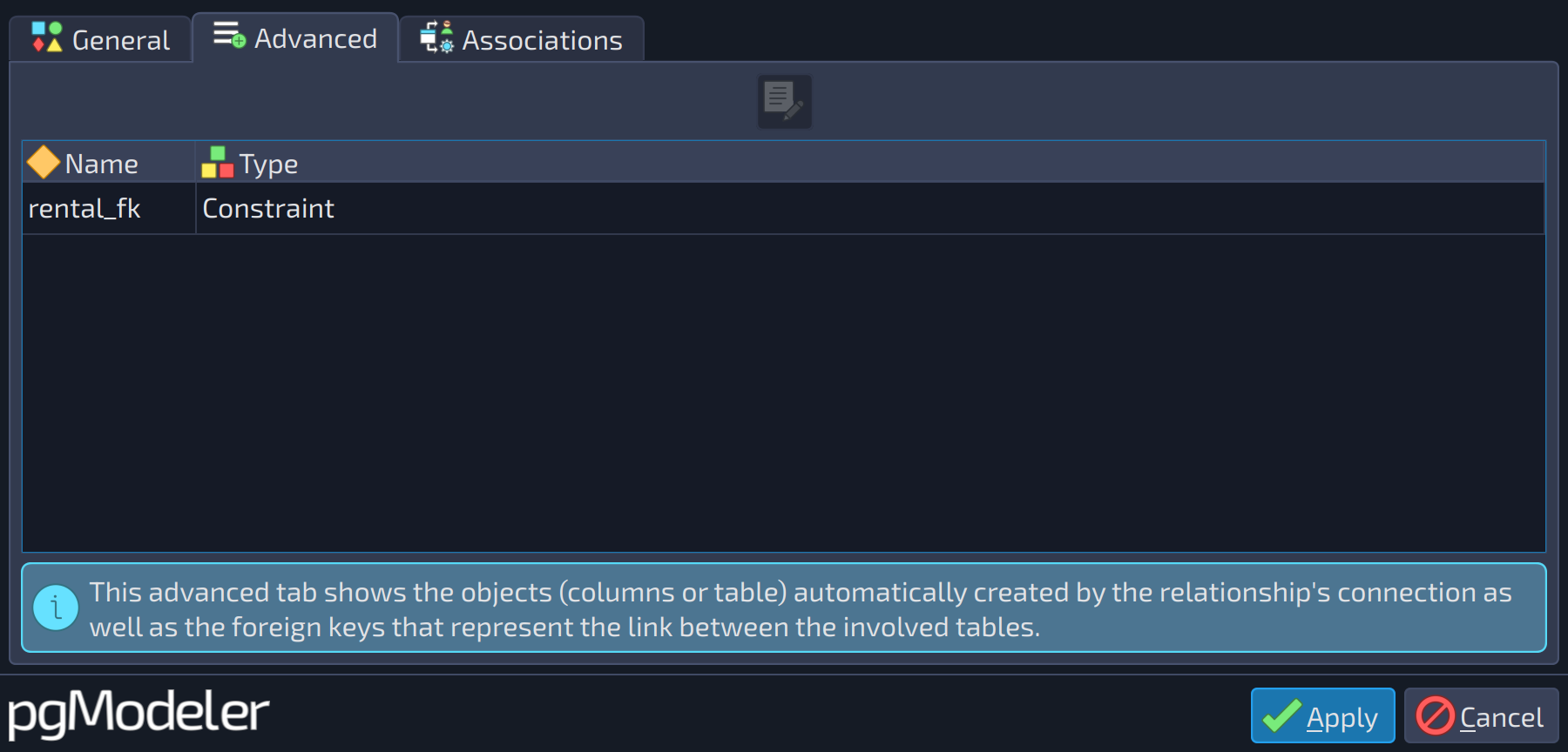
The editing form of an fk relationship shows the following tabs:
 1234
1234
| General | |||
|---|---|---|---|
| # | Field | Group box | Description |
| 1 | Referrer table | The table that owns the foreign key (the (n) side of the relationship). | |
| 2 | Referenced table | The table referenced by the foreign key (the (1) side of the relationship). | |
| 3 | Custom line color | Options | Draws the relationship line with a custom color instead of the default one. The color button and the random color button are enabled when it is checked. |
| 4 | Line color | Options | Selects the color used to draw the relationship line when |
 1
1
| Advanced | ||
|---|---|---|
| # | Field | Description |
| 1 | Generated objects | The foreign key that represents the relationship. Opening it shows its editing form in read-only mode. |
Dependency
This relationship is similar to the copy one in style and semantics, but it's applied to denote a link between a table and a view. Additionally, this object can't own attributes or constraints, and the user can only handle its name and label position.
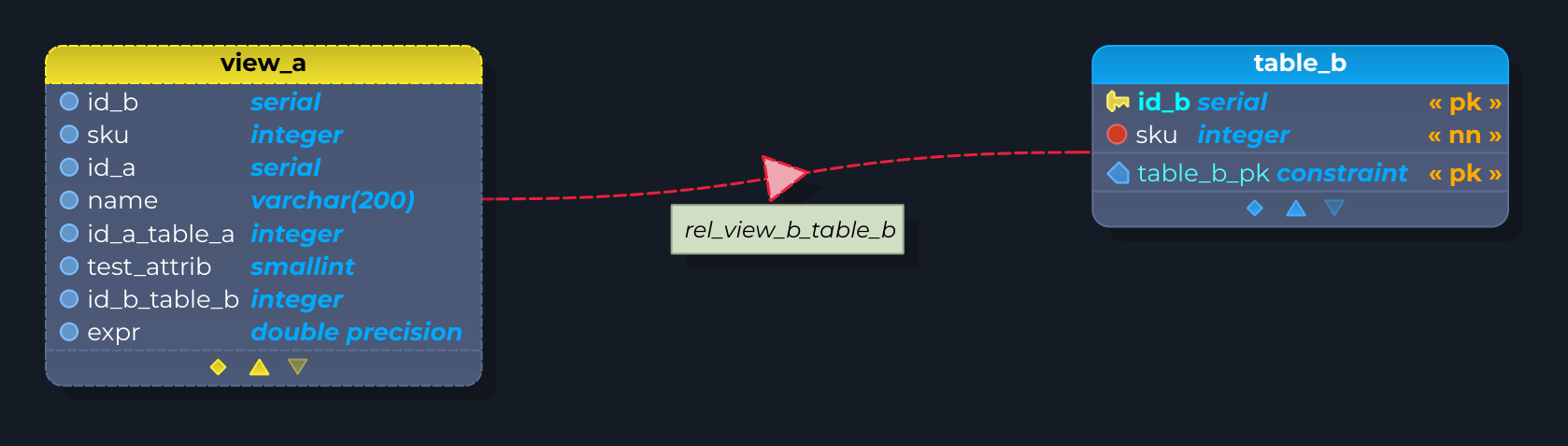
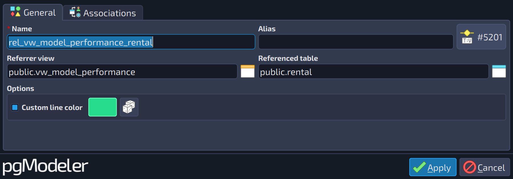
The editing form of a dependency relationship is the following:
 1234
1234
| General | |||
|---|---|---|---|
| # | Field | Group box | Description |
| 1 | Referrer view | The view that references the columns of the table. | |
| 2 | Referenced table | The table whose columns are referenced by the view. | |
| 3 | Custom line color | Options | Draws the relationship line with a custom color instead of the default one. The color button and the random color button are enabled when it is checked. |
| 4 | Line color | Options | Selects the color used to draw the relationship line when |
Identifier relationship
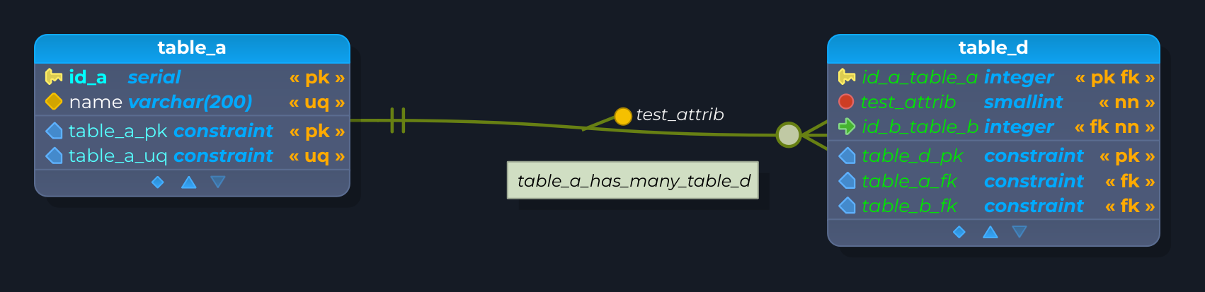
This relationship implements the concept of strong and weak entities. Basically, the weak entity (tableB in the image below) is the table in which tuples only exist when the referenced tuples on the strong entity (tableA) also exist. This means that if the item on the strong entity is deleted, all the items on the weak entity that reference the deleted one are removed as well.
Additionally, this relationship creates a primary key on the weak entity hence the name identifier relationship. If a primary key already exists on the weak entity, the created primary key is merged into the existing one. Finally, this kind of relationship is graphically identifiable by the thick line linked to the weak entity. Also, only one-to-one and one-to-many relationships can be marked as identifiers.
Partitioning relationship
In PostgreSQL, table partitioning refers to the action of splitting one large table into smaller physical pieces. There are several benefits that we can gain from this technique, for instance, improved query performance, separation of data that is frequently accessed from seldom-accessed data, and many others. In previous pgModeler releases, there were some ways to simulate table partitioning (as well as in PostgreSQL 9.6 and below) by using a combination of inheritance and triggers, which could be very difficult to maintain in certain situations. Since pgModeler 0.9.2, declarative table partitioning (introduced by PostgreSQL 10 and improved in version 11) is supported, making partitioning easier to create and maintain.
In pgModeler, table partitioning is configured by using three features: the partitioning strategy, the partition keys (both configured in the partitioned table), and a partitioning relationship. The partitioning strategy, or simply partitioning, is the mode in which PostgreSQL will handle the data separation in the main table (called the partitioned table) and in its partitions. There are three supported partitioning modes: LIST, RANGE, and HASH. The partition keys are a set of columns of the partitioned table or expressions that are used to define the key columns or values used to determine the correct partition to which the inserted data will be routed, for instance. Finally, a partitioning relationship is used to denote graphically that a table is a partition of another, as well as to configure the partition bounding expression that is used to route the data to a specific partition based on the value(s) in it.
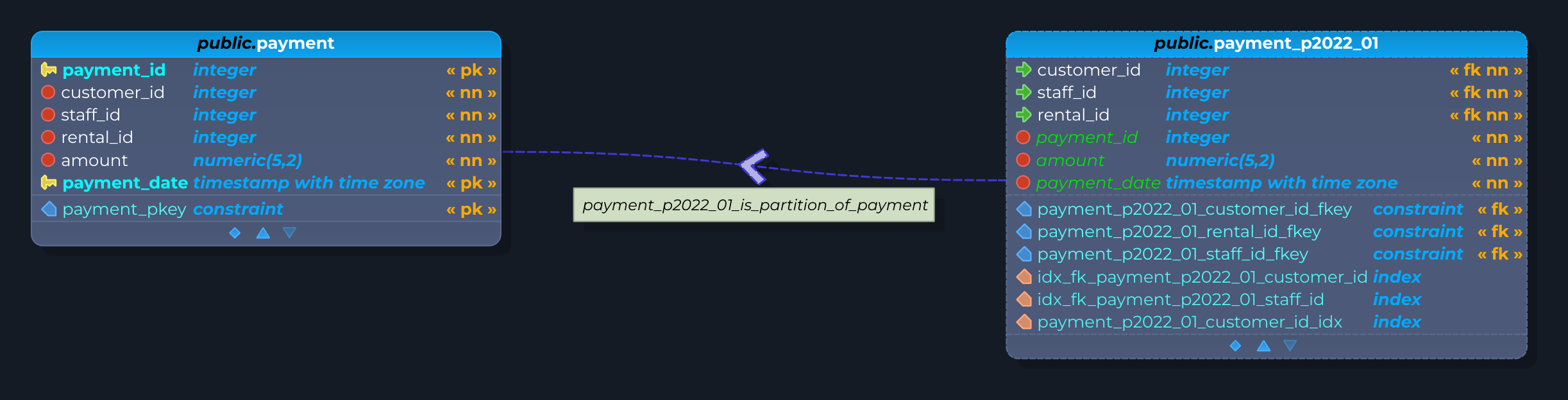
The syntax of the bounding expression is tied to the partitioning strategy adopted and has different forms of writing, thus pgModeler helps the users by creating a template expression when a new partitioning relationship is being created.
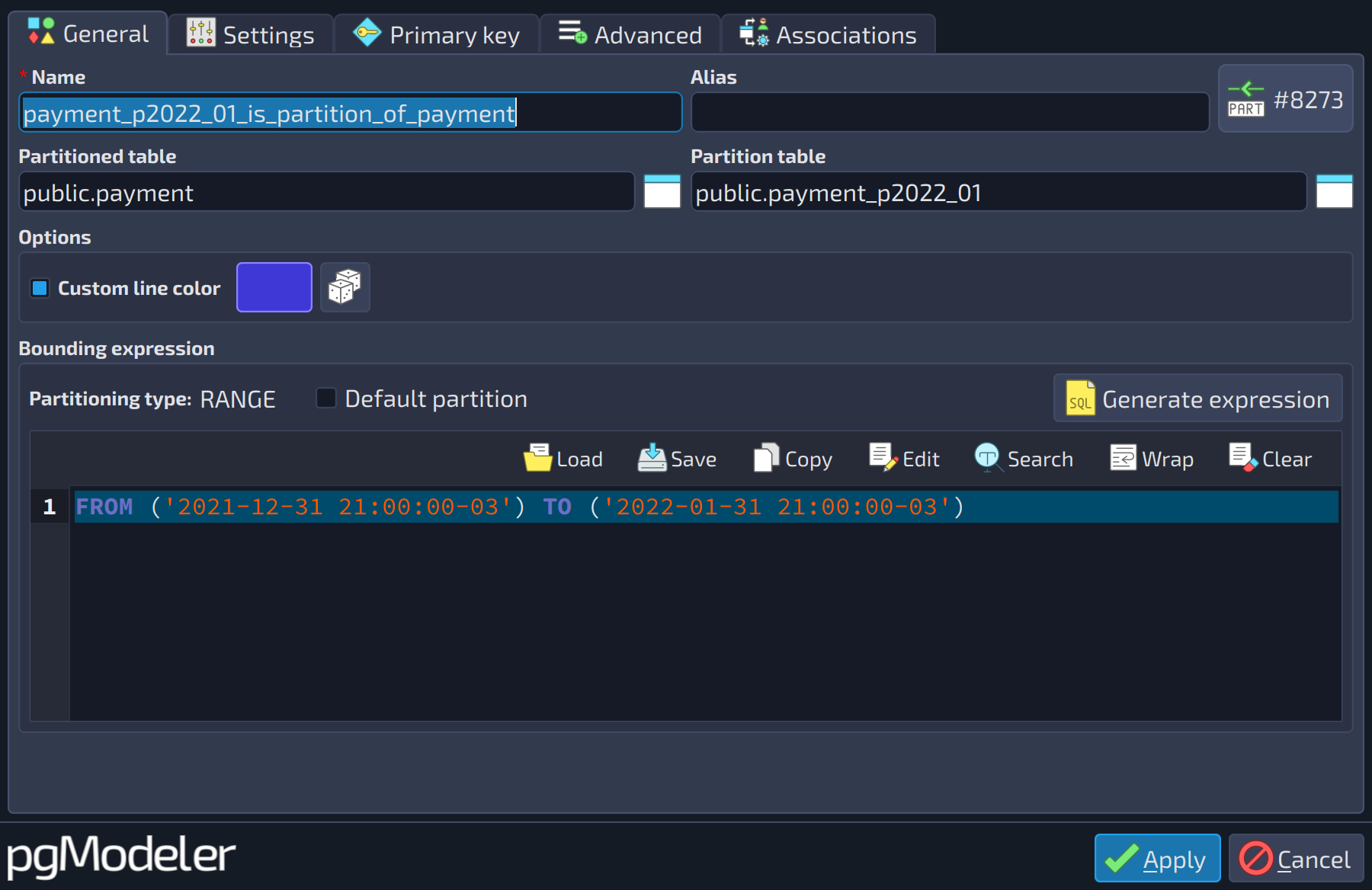 1234567
| General | |||
|---|---|---|---|
| # | Field | Group box | Description |
| 1 | Partitioned table | The table that is split into smaller pieces (the partitions). The partitioning strategy is defined in this table. | |
| 2 | Partition table | The table attached to the partitioned table, where the data routed by the partitioning rule is stored. | |
| 3 | Custom line color | Options | Draws the relationship line with a custom color instead of the default one. The color button and the random color button are enabled when it is checked. |
| 4 | Line color | Options | Selects the color used to draw the relationship line when |
| 5 | Default partition | Bounding expression | Default partitions are only supported on PostgreSQL 11+. Using this option and exporting the code to PostgreSQL 10 syntax errors will be raised. |
| 6 | Generate expression | Bounding expression | Generate the partition bounding expression based upon the partitioning type in use. |
| 7 | Bounding expression | The bounding expression of the partition. Its syntax depends on the partitioning strategy of the partitioned table; the button | |
In the image above, we have a small partitioning hierarchy created. The relationship between table_a (partitioned) and table_b (partition) is a partitioning relationship denoting that table_a somehow will "redirect" data to table_b when some conditions are met. Note that the partitioning relationship has its own descriptor or identifier: an arrow always pointing from the partition table to the related partitioned table, which makes its representation unique among all kinds of relationships. Even the relationship's name label enforces that it represents a link between a partition and its partitioned table.
Still in the image, in the table properties dialog, the highlighted section contains the partitioning strategy used by table_a as well the partition key(s) (in the grid at the bottom) for the partitioning hierarchy. Now, in the relationship properties dialog, the highlighted area is the partition bounding expression used to define values of the partition key defined in table_a which will be routed to table_b.
Attributes and constraints
Attributes are visually represented by the orange circles that appear next to the relationship descriptor (in classical ER notation) or in the center of the line (in crow's foot notation) and are nothing more than columns assigned to the relationship. These attributes are inserted into the tables when the relationship is connected to the entities.
Relationship constraints are the same as the ones used for tables, but the only difference is that they can only reference relationship attributes. These objects are added to tables like the relationship attributes. Except for primary keys, all other types of constraints can be created in the relationships. Primary keys are treated in a special way as described in the next section.
 1
1
| Attributes | ||
|---|---|---|
| # | Field | Description |
| 1 | Attributes | The attributes of the relationship, which are converted into columns of the receiver table when the relationship is validated and connected. Available only for one-to-one, one-to-many, and many-to-many relationships. |
 1
1
| Constraints | ||
|---|---|---|
| # | Field | Description |
| 1 | Constraints | The constraints of the relationship, which can reference only the relationship attributes. Available only for one-to-one, one-to-many, and many-to-many relationships. |
Editing form
Being the most complex objects in pgModeler, relationships have an editing form that tries to minimize this complexity by separating fields into different sections. This dialog is a polymorphic one, meaning that some fields will be absent depending on the relationship type. All the fields in the form are described below. The General section is where the basic details of the relationship are configured. They are detailed in the next table.
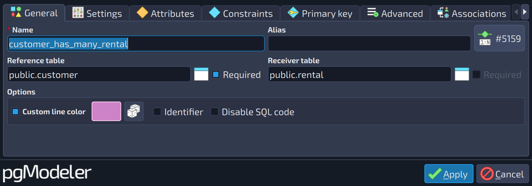 1234567
| General | |||
|---|---|---|---|
| # | Field | Group box | Description |
| 1 | Reference table | The table whose primary key columns are copied, as foreign key columns, to the receiver table. | |
| 2 | Required (reference table) | Marks the participation of the reference table as mandatory (cardinality (1,1)): the generated foreign key columns are created as | |
| 3 | Receiver table | The table that receives the columns copied from the reference table. For many-to-many relationships, this field is renamed to | |
| 4 | Required (receiver table) | Marks the participation of the receiver table as mandatory. It is enabled only for one-to-one relationships and is disabled when | |
| 5 | Custom line color | Options | Specifies a custom color for the relationship line and descriptor. |
| 6 | Line color | Options | Selects the color used to draw the relationship line when |
| 7 | Identifier | Options | Marks the relationship as an identifier: the primary key of the receiver table is composed of the generated foreign key columns. This option is available only for one-to-one and one-to-many relationships that are not self-relationships. |
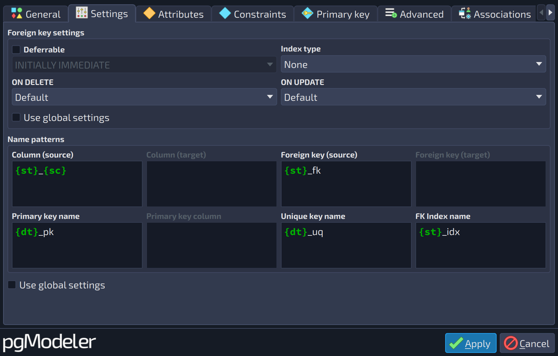 123456789101112131415
| Settings | |||
|---|---|---|---|
| # | Field | Group box | Description |
| 1 | Deferrable | Foreign key settings | Makes the generated foreign key deferrable. The deferral mode is configurable only when this option is checked. |
| 2 | Deferral | Foreign key settings | When a deferrable foreign key is checked: |
| 3 | Index type | Foreign key settings | Creates an index on the columns of the generated foreign key using the chosen access method. |
| 4 | ON DELETE | Foreign key settings | The action taken when a referenced row is deleted. With |
| 5 | ON UPDATE | Foreign key settings | The action taken when a referenced row is updated. With |
| 6 | Use global settings | Foreign key settings | Use the values defined on settings dialogs for the fields below |
| 7 | Column (source) | Name patterns | Pattern for columns generated based upon reference table's pk (1-1 and 1-n) or based upon source table's pk (n-n). |
| 8 | Column (target) | Name patterns | Pattern for columns generated based upon target table's pk (n-n). |
| 9 | Foreign key (source) | Name patterns | Pattern for foreign key generated based upon reference table's pk (1-1 and 1-n) or based upon source table's pk (n-n). |
| 10 | Foreign key (target) | Name patterns | Pattern for foreign key generated based upon target table's pk (n-n). |
| 11 | Primary key name | Name patterns | Pattern for primary key generated by identifier relationship. |
| 12 | Primary key column | Name patterns | Pattern for primary key generated by identifier relationship. |
| 13 | Unique key name | Name patterns | Pattern for unique key generated by the relationship. |
| 14 | FK Index name | Name patterns | Name pattern of the index created for the foreign key (see the tokens in the section about name patterns). It is enabled only for one-to-one, one-to-many, and many-to-many relationships. |
| 15 | Use global settings | Use the values defined in settings dialogs for the fields below | |
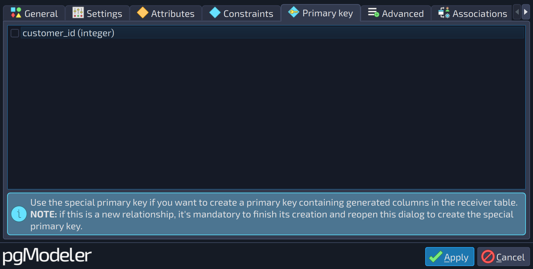 1
1
| Primary key | ||
|---|---|---|
| # | Field | Description |
| 1 | Primary key columns | The columns generated by the relationship, along with its attributes, that compose the special relationship primary key. The constraint is added to the receiver table when the relationship is connected. |
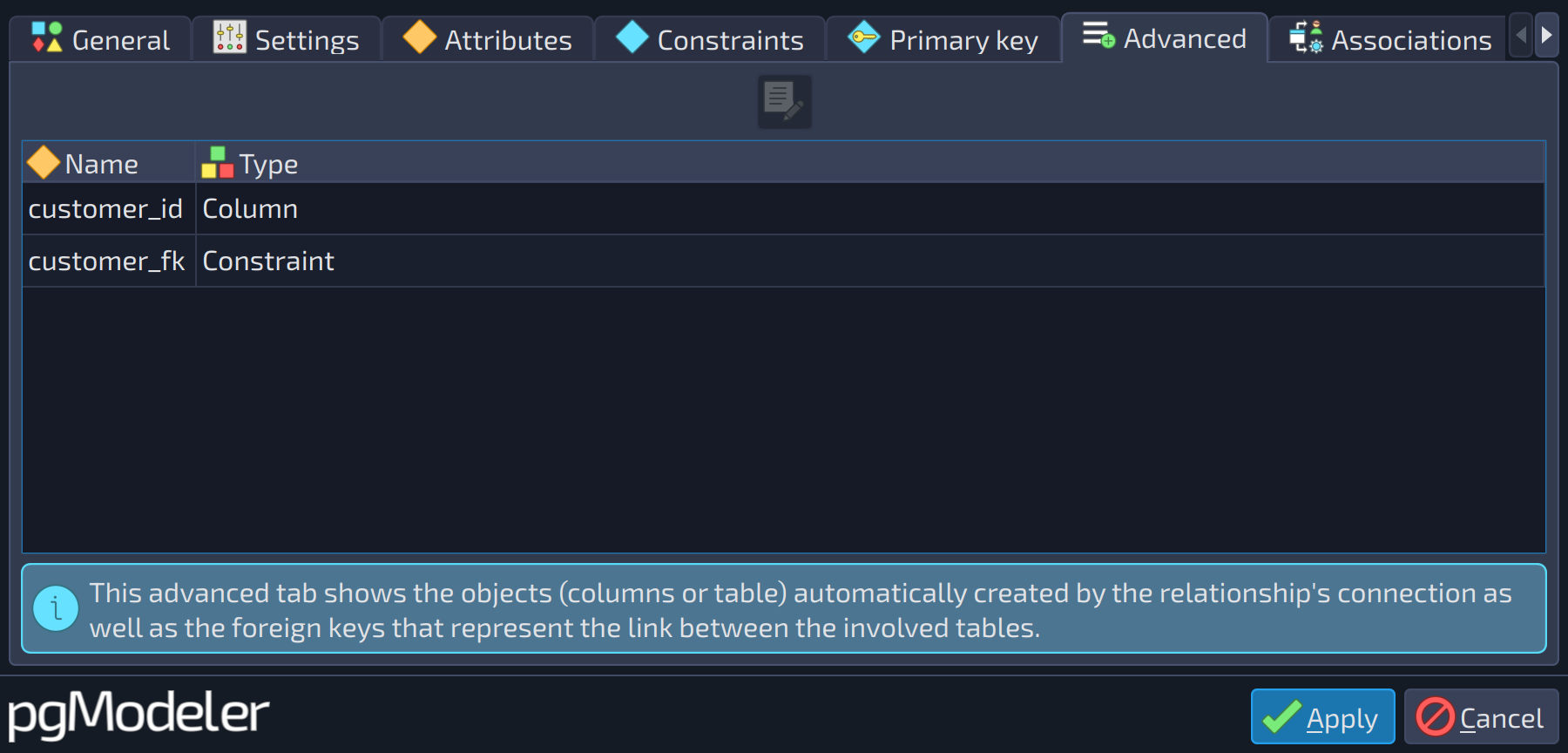 1
1
| Advanced | ||
|---|---|---|
| # | Field | Description |
| 1 | Generated objects | The objects generated by the relationship (columns, tables, and the foreign keys that represent the link). Opening one of them shows its editing form in read-only mode. |
The relationship type is shown, in a read-only way, by the icon button at the top right corner of the dialog (together with the object ID): one-to-one (1-1), one-to-many (1-n), many-to-many (n-n), generalization or inheritance (gen), copy (dep), partitioning (part), fk relationship (fk), and the dependency between a table and a view (tv). Some fields appear only for specific types:
- Required (beside each table selector): marks the tables of mandatory participation (cardinality). Available only for one-to-one and one-to-many relationships.
- Generated table name and Single PK column: used only in many-to-many relationships. The first sets the name of the intermediate table; when the second is checked, the intermediate table receives an extra
serialcolumn used as its single primary key column instead of a primary key composed of the columns of both foreign keys. - Copy options: used only in copy relationships. Indicates which attributes must be copied from the reference table. You can include or exclude some attributes, or use the default behavior, which is to copy only column names, their data types, and not-null constraints. The attributes that can be copied are
DEFAULTS,CONSTRAINTS,INDEXES,STORAGE,COMMENTS,STATISTICS,IDENTITY, orALL. - Bounding expression (with Default partition and Generate expression): used only in partitioning relationships, as described in the section about them.
- The tabs Attributes and Constraints are available only for one-to-one, one-to-many, and many-to-many relationships, and the tab Settings is not available for all kinds of relationships; its group Name patterns is described in the next section.
Name patterns
Column propagation is a powerful mechanism implemented by pgModeler. It can accelerate productivity by automatically creating columns and constraints as the user links tables using relationships. The only downside of this feature is the lock-in of any created object, meaning that the user can't change any of their attributes, including names. To work around this issue, pgModeler can define name patterns that are parsed during relationship creation time and used to generate the name of any object allocated.
Basically, patterns are a combination of predefined tokens and additional characters added by the user. Four tokens are recognized: {sc}, {st}, {dt}, and {gt}. Note that any token must be enclosed in {} to be parsed by pgModeler. The meaning of each token is described below:
{sc}: stands for the name of the source column or the primary key column used as a reference.{st}: stands for the name of the source or reference table.{dt}: stands for the name of the destination or receiver table.{gt}: stands for the name of the generated (or most commonly, the intermediate) table name. This token is used only when the relationship is of type many-to-many.
To clarify the token usage, let's take a look at the image below. The relationship links tableA to tableB, in this case, the first is the source or reference, and the last one is the destination or receiver, because it is the table that receives all generated objects. Note the column tableA_id on tableB, this column was generated through the pattern {st}_{sc} where {st} is replaced by the name of the reference table, tableA, and {sc} replaced by the primary key column id of that table.
The same rule is valid for the generated foreign key tableA_fk; the name pattern used was {st}_fk. In this case, there is a static text _fk that is kept when pgModeler translates the pattern because the text is not enclosed by {} as the rule states. The user can specify at most eight name patterns, namely: two for columns, two for generated foreign keys, two for the primary keys, one for the generated unique key, and one for the index generated for columns created by the relationship. Not all fields will be enabled at the same time because the use of a specific name pattern is conditioned on the relationship type currently being handled.
Starting with version 2.0, the default patterns follow a table-first convention: the column patterns are {st}_{sc} (and {dt}_{sc} for the second column of many-to-many relationships), whereas in previous versions they were {sc}_{st} and {sc}_{dt}, which produced names like id_tableA. The default of the foreign key index pattern is {st}_idx ({gt}_idx for many-to-many relationships). If you upgraded from a previous version, review the file relationships.conf of your settings, since it keeps the patterns you had, or restore the defaults in the Relationships section of the settings.
References
Table partitioning feature
https://www.postgresql.org/docs/current/ddl-partitioning.html